I am writing this as more of a informal documentation of the project rather than a blog post. I have defended the thesis in late January 2021 and since then finished my other Bachelors (Computer Science), with thesis also focused on motorsport aerodynamics, so it will also be described here. The full text can be downloaded here:
https://drive.google.com/file/d/1o1KS-KUtfVfkCbLEPruvO6RI8QBfevaM/view?usp=sharing
Introduction


Okay, so getting there really took me around 9 months from pretty much exactly the year between my thesis advisor agreeing to help me with the project, and me sending a finished PDF to the anti-plagiarism system. And I think at least two of these were spent solely on getting a proper, watertight geometry, with no bad edges or surfaces. This obviously was caused by me misusing the Realize Shape tool - while it is indeed an incredibly powerful tool, its resulting geometry was far from what I needed, and joining it with parametrically-defined surfaces was a pain in the neck. Next time I'm going to use it solely as a shape research tool, and not a way to make a final geometry. Apart of these problems, in order to reach the detail level I wanted, I made the freeform surface overly complex, which is a problem, because every increase in level of detail is equal to at least one more surface:

This is a problem, because the mesher does not understand that some connections are continuous and some are not. Having many small surfaces means a lot more work for the mesher.
Mesh
Speaking of the mesh, having such a geometry meant that mesh generation was problematic. At first I attempted to use ANSYS Meshing module, which in the end never really worked because of a few small surfaces, making a change in one caused the error move to the other. In the end my thesis advisor told me to use Fluent meshing, which showed some errors, but generated the mesh nevertheless. Because I was constrained to my own personal PC, the final mesh couldn't be too dense, still I wanted it to be dense enough for the results to be at least somewhat realistic. Finally, I ended up with 1 cm cells on the surface except the rear wing, where 1 mm cells were used. Entire car surface was covered with boundary layer inflation layers. If you're interested in the details, look into section 4.1.
Solution
Once the mesh was generated, a converging solution was not much of a problem. The results were very underwhelming though. A downforce coefficient of little over 0.8 with drag coefficient of just under 0.6 is just disappointint. Since the geometry was a bloody mess and the time was running up, the only way to go was to analyse what went wrong (and yeah, there was quite a bit of that).
Aerodynamic design in detail (aka The Theory)
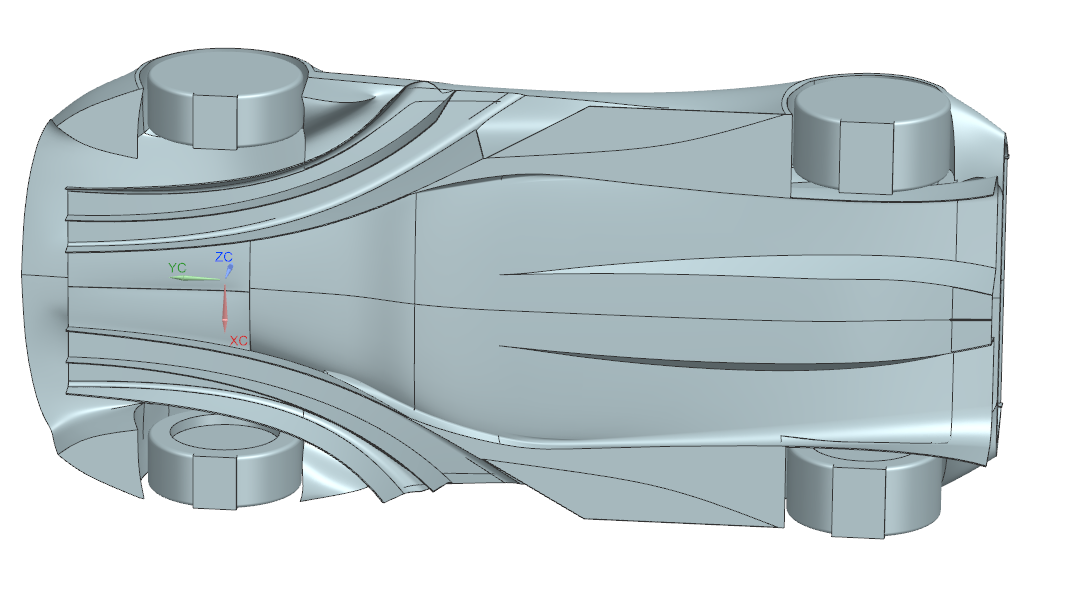
Before I go through the CFD plots, I think it would be beneficial to present the body in a bit closer detail to explain some of the decisions I made. If you haven't guessed that already, all of that is based on "educated guesses" and hope that it would work. Bad CAD methodology and lack of time meant no improvements were made over initial designs. Nevertheless, here they are:
The underbody was basically a merge of what I thought Valkyrie looked like with Elemental RP1. The flow was supposed to go through the front tunnels, and the rest of it should go into the rear ones. Unlike the Valkyrie and RP1 (in my current opinion), there was no good enough vorticity generation at the start of both front and rear tunnels, and tunnels based solely on Bernoulli are just weak. On the other hand, tunnels in 2022 F1 cars start in a similar way. Maybe there is a different mechanism I don't know about.
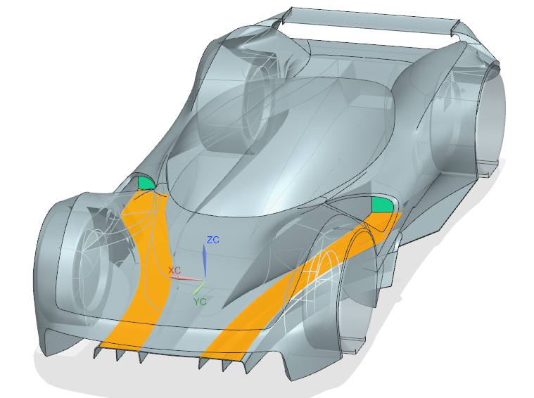
Utilizing crazy single seater-like cockpit inspired by Valkyrie was supposed to introduce multiple benefits, most important being ability to utilize and redirect internal flow. The front tunnels can be used to guide the air both to the side radiator, and outside of the car, minimizing drag.

This sidepod-like design could be used to run the channels through an entire car.
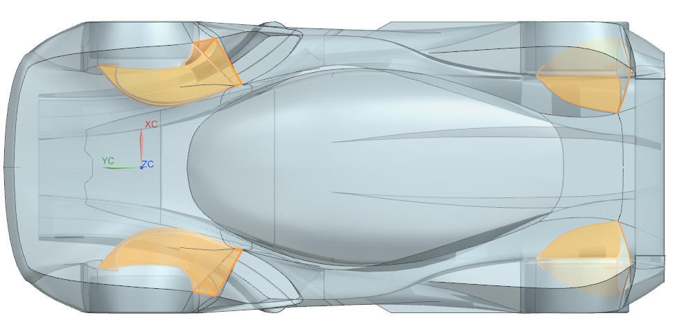
Wheel well outlets were kind of necessary in the car of this type, and also fitted nice into the design.
All in all, this looks very nice, but what about functionality?
CFD results analysis (aka The Practice)
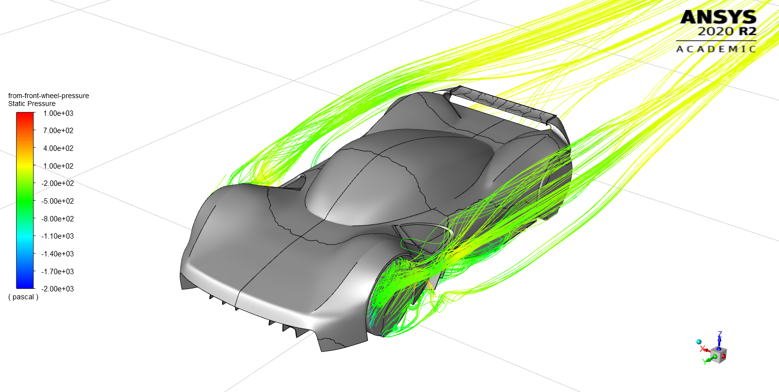
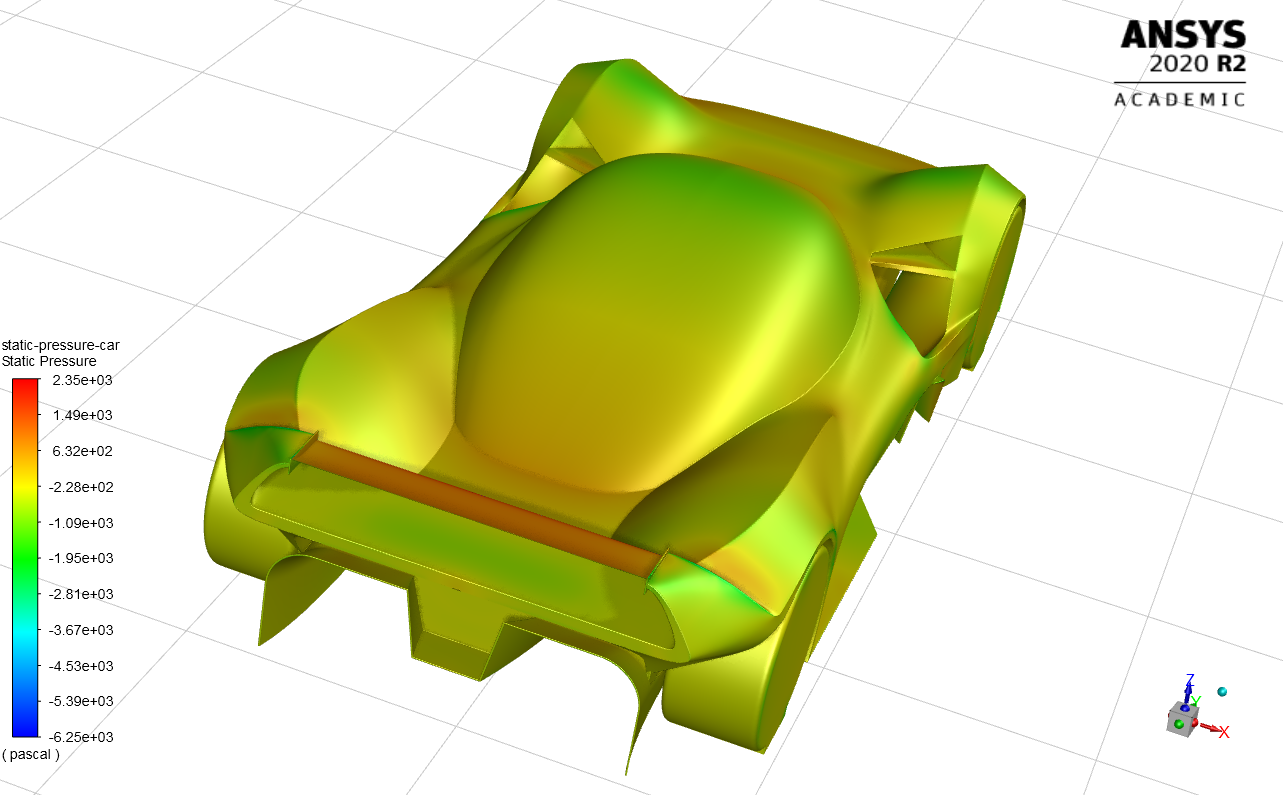
Let's go into the pressure contour plots.
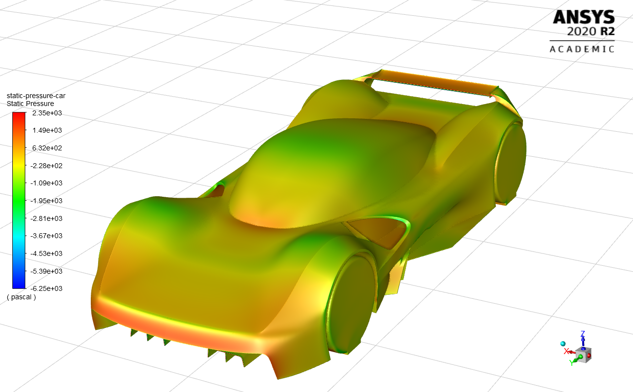
The pressure plot shows pressure buildup on the most forward face followed by the separation. As expected, The most upward-protruding surfaces (i.e. front fenders and the roof canopy) are areas of low pressure.
Nothing out of the ordinary on the back as well. My designer-ish wing supports can be seen generating some drag.

Now, here is where all of the problems start. Starting on the front, sharp edge is a source of separation. Then there are the front tunnels. Interestingly, a negative pressure is generated only in the outer section (even then it's not very strong). While the horizontal surface connecting the front tunnels probably generates some local downforce, it also directs the air straight into the monocoque, creating a large area of positive pressure. Next we have what we wanted - a large area of negative pressure. While in the right place (almost exactly between the axles), it is nowhere near the strength expected for such a shape. The plot shows almost no pressure variation inside rear tunnels.

An interesting way to visualize pressure is to plot a zero static pressure "bubble" - plot a surface where static pressure equals to zero, indicating the transition from positive to negative pressure areas and vice versa. The bubble is expected at the front of the canopy, but not behind it. Maybe a smoother transition would help. Also the bubble out of the front tunnels ends rather close to the car - maybe the vortex is not strong enough and therefore ends quickly. The other big bubble is there around the side outlet - I don't know how to interpret this. The other small bubbles are expected and mostly happen due to the bad geometry.
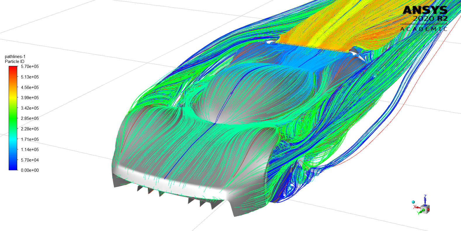
If we turn on all streamlines, we mostly see two vortices shedding of each front wheel. Rest of the flow is too messy.

Starting streamlines off front wheels reveals the first probable major issue - the messy flow from the front wheels enters the front wheels, heavily disrupting the flow (in the end there was probably not much to disrupt, but let's not dwell on that). Maybe this is the reason for LMP1's front tunnels being sealed from the bottom.
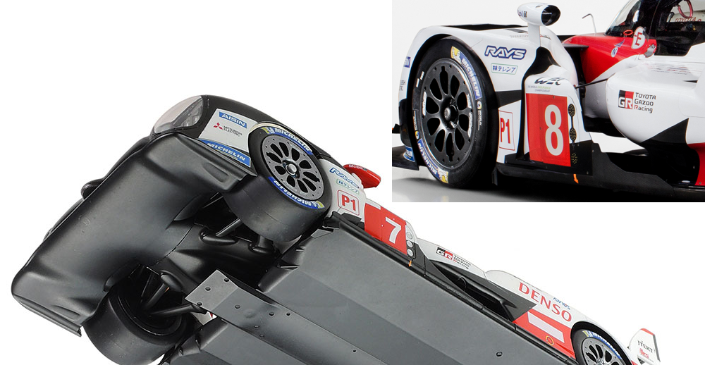
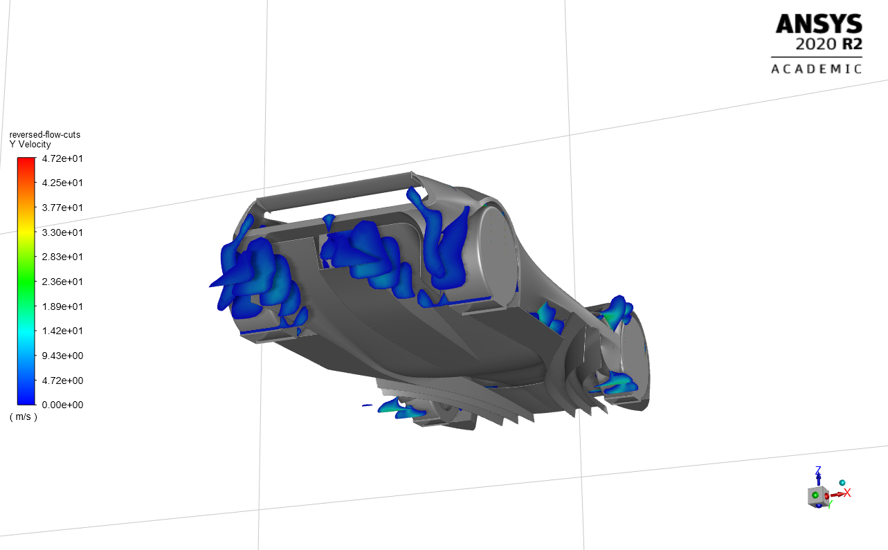
Rear tunnel flow appears to be disrupted as well. In the picture above I showed the areas of reversed flow. Wake from the rear wheels returns into the rear tunnels. Closer look into Valkyrie shows that it has curved bottom edge extensions.
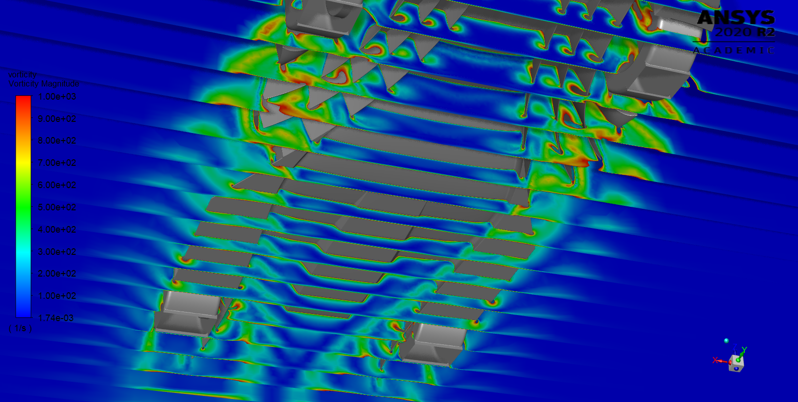
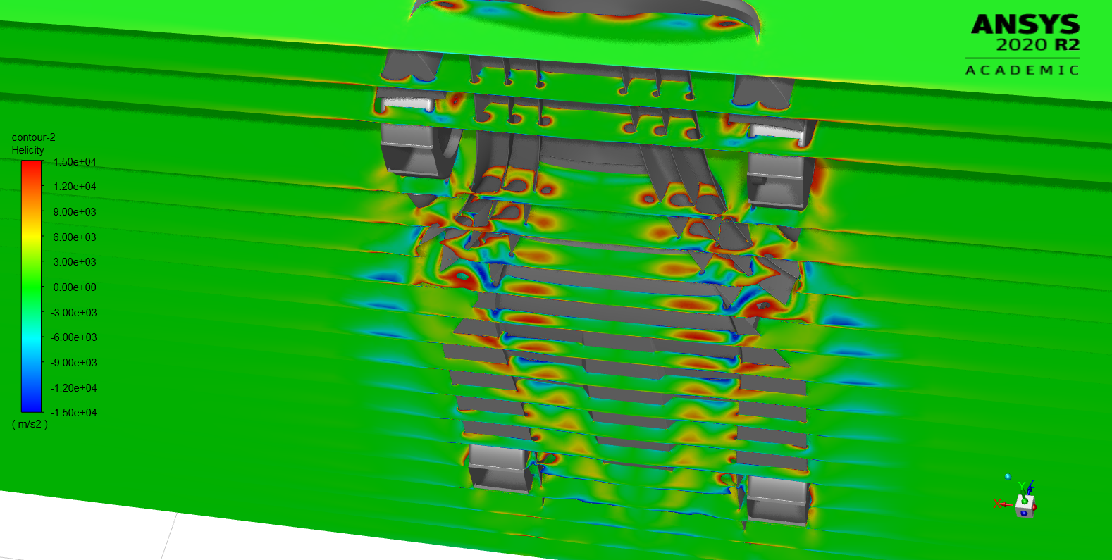
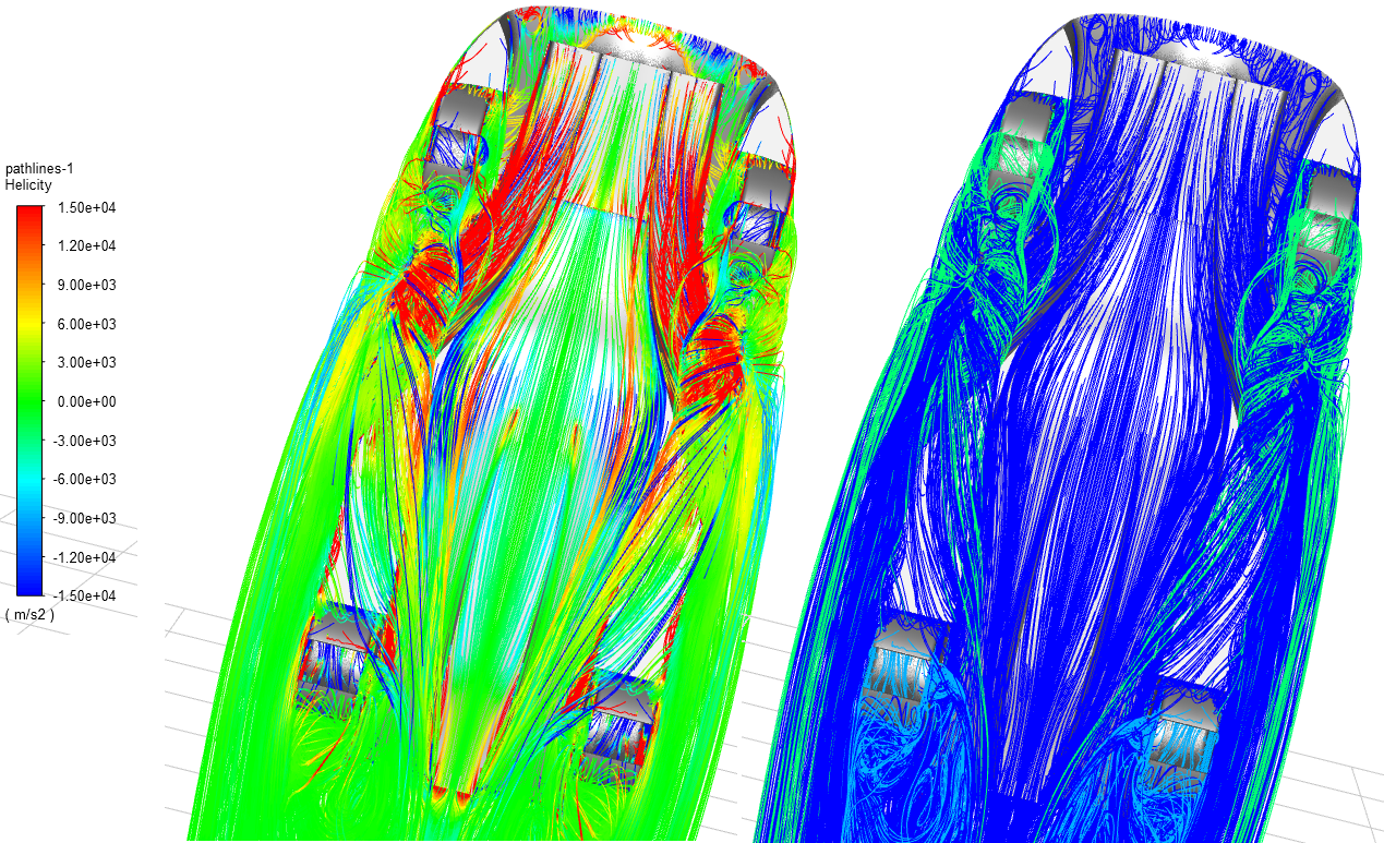
The three posts above are vorticity and helicity contours and helicity-colored pathlines. The plots confirm previous suspicions (wheel wake entering front and rear tunnels), and also highlight two more problems - outer flow feeding into rear tunnels and minimal vorticity at the rear tunnels. I also did an oil flow visualization on the bottom surface. Straight lines and no vortices at all.

There are few other plots in the paper, but the problems are apparent enough. I also did a transient simulation to show areas most prone to separation (constant Q criterion bubble).
Conclusions
Stuff went bad and there was no time or ability to fix it. Still, I've learned a ton. Since I've finished the thesis I've found a 3D model of Valkyrie from a mobile game that appears to be legit (i.e. provided by Aston Martin or developed with its help). While the model is developed from the game and definitely not enough for CFD. Maybe I'll make a new model based on this one.
No comments:
Post a Comment